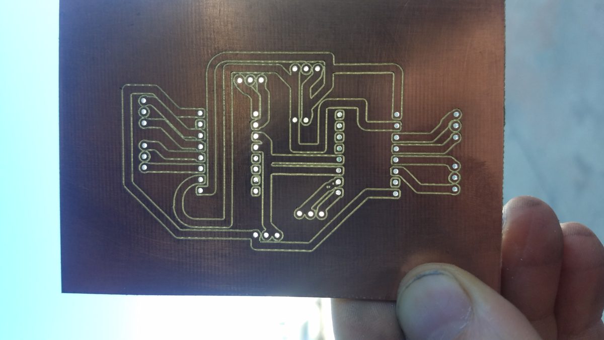
In order to better speed up my prototyping and in consideration of possibly small scale manufacturing I have begun milling my circuit board designs.
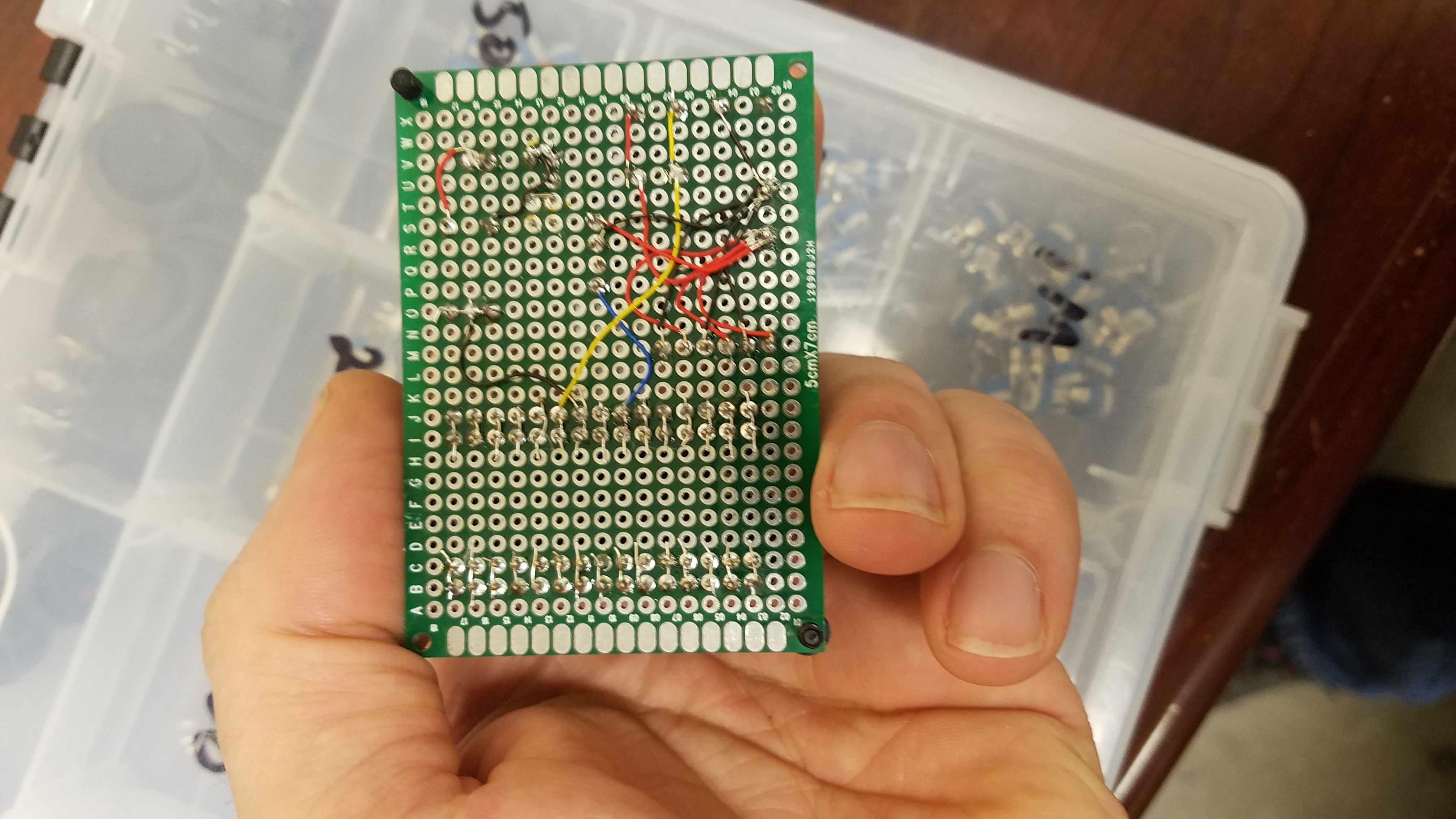
This picture should give you a clear idea why this is so important. This is how myself, and many others, make circuit boards at home. By wrapping wire around the back and soldering in place. Its tedious and error prone.
I haven’t mastered it yet by any means but I can tell you about my journey and give you some tips. I’m using a self made CNC machine. Everything I used is off the shelf.
Design
I used Eagle to make the design. Its a popular software and free to use for non commercial. There’s so much to say on the subject of design and using the eagle software. Kicad is another. Not super easy to use and it gets a bit tougher if you want to export to a machine for production. After you make you schematic you click generate your board.
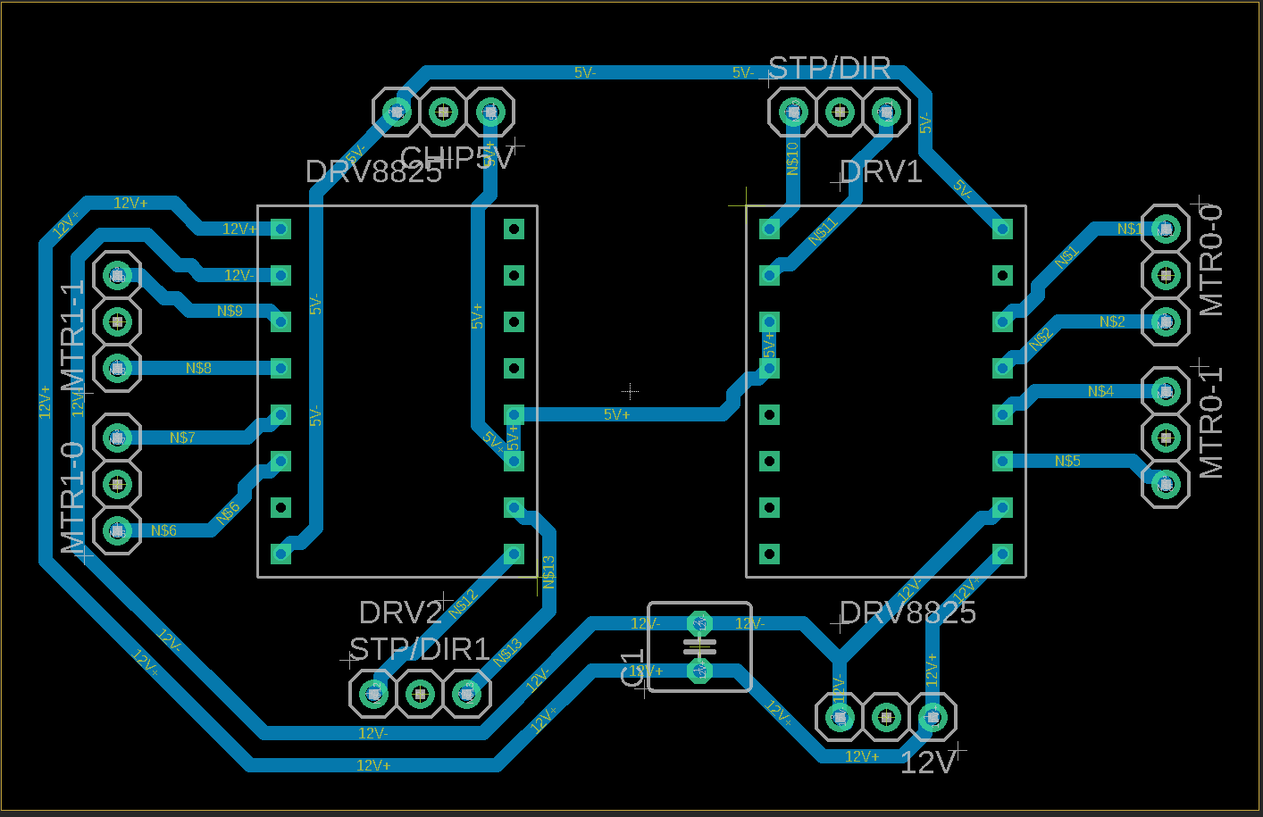
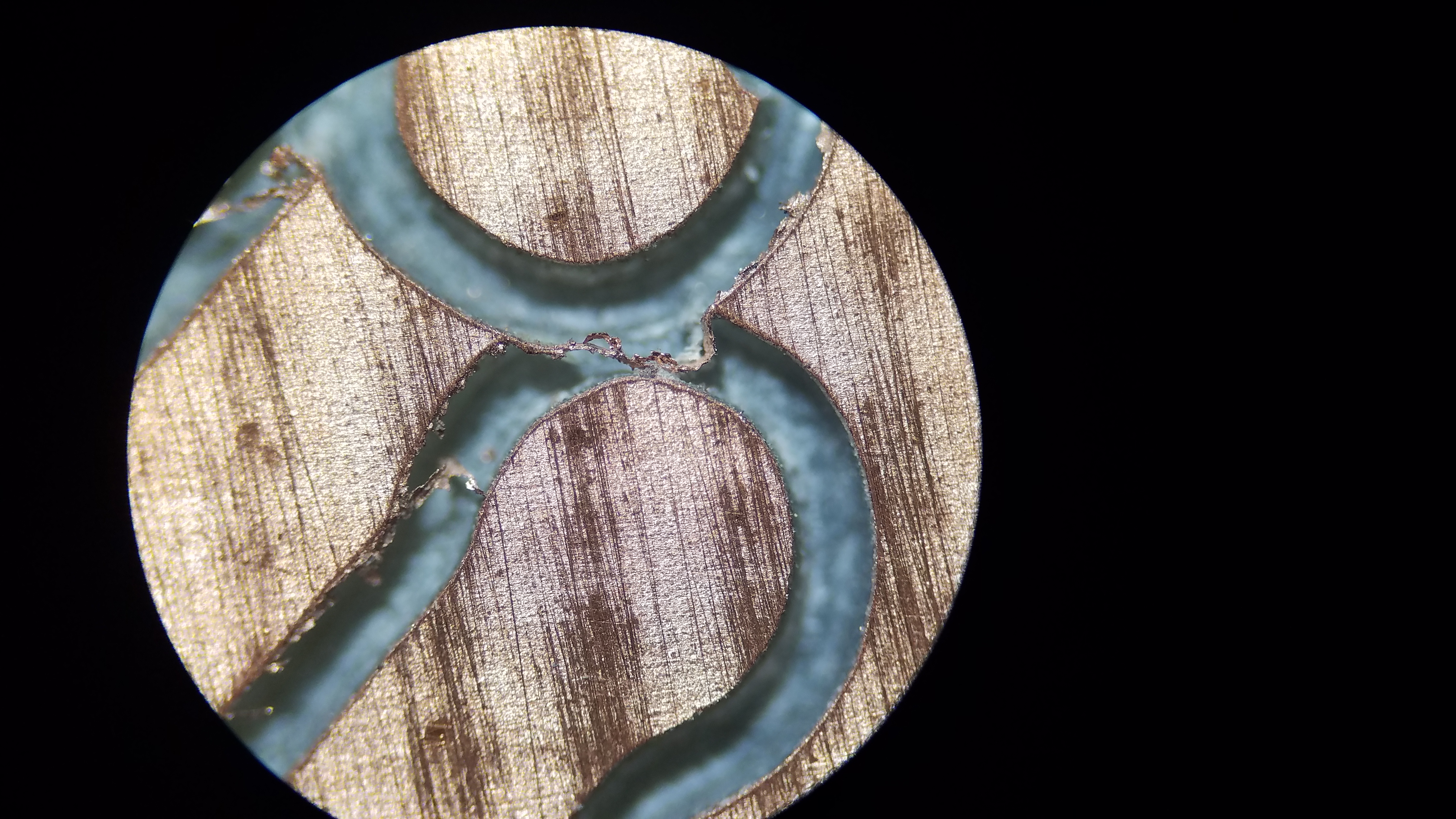
- You need to set the net thickness and spacing sizes based on your machine, bits, and personal skill. I chose 30 mil size and 40 mil space.
- The measurements are not millimeters but thousands of an inch. Leave it that way and convert. Otherwise you’ll be fighting the software.
- Your origin is at the bottom left. After making you design you need to drag the entire thing to center it over your origin if you want to start your machine off in the center.
There’s a lot more to be said but I suggest you watch some tutorial or do research as needed. Use the cam processor and create your gerber files excellon file for next step
Creating G-Code to execute
A free software called flatcam can be used to transform the gerber files and excellon drill files into gcode. For simplicity same I made my project by using only two files the bottom.gerber and the drill.xls
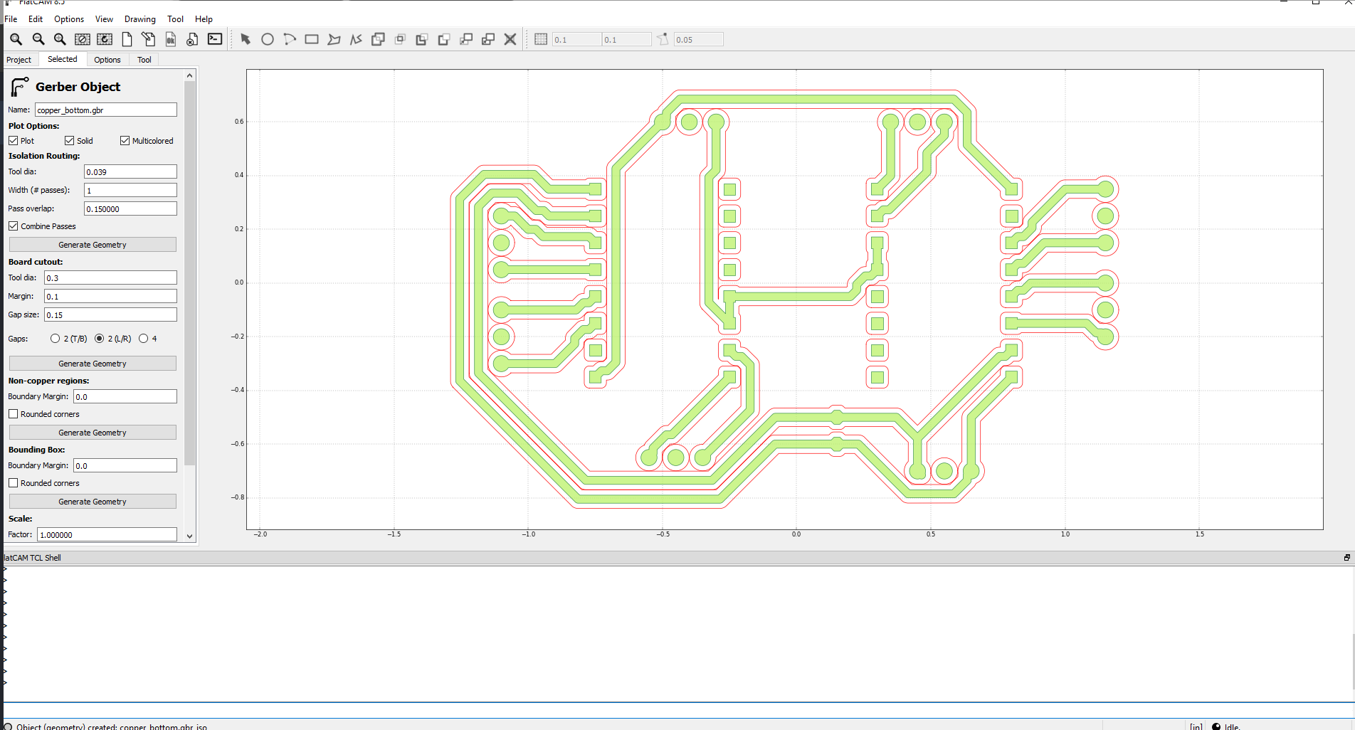
Flatcam creates a tool path to isolate your circuits by using the layout and your input. A few key things.
- Your tool size must be smaller than the net spacing you entered in eagle. Otherwise it wont try and cam that area and you will have gaps. I chose .039 as my tool size which is a hair smaller than the 40 mil I put in eagle and is about 1mm for my sanity.
- I chose .5 for z travel because I have a floating Z I need .25 inches to lift the float and .25 for clearance. You will see more on floating below.
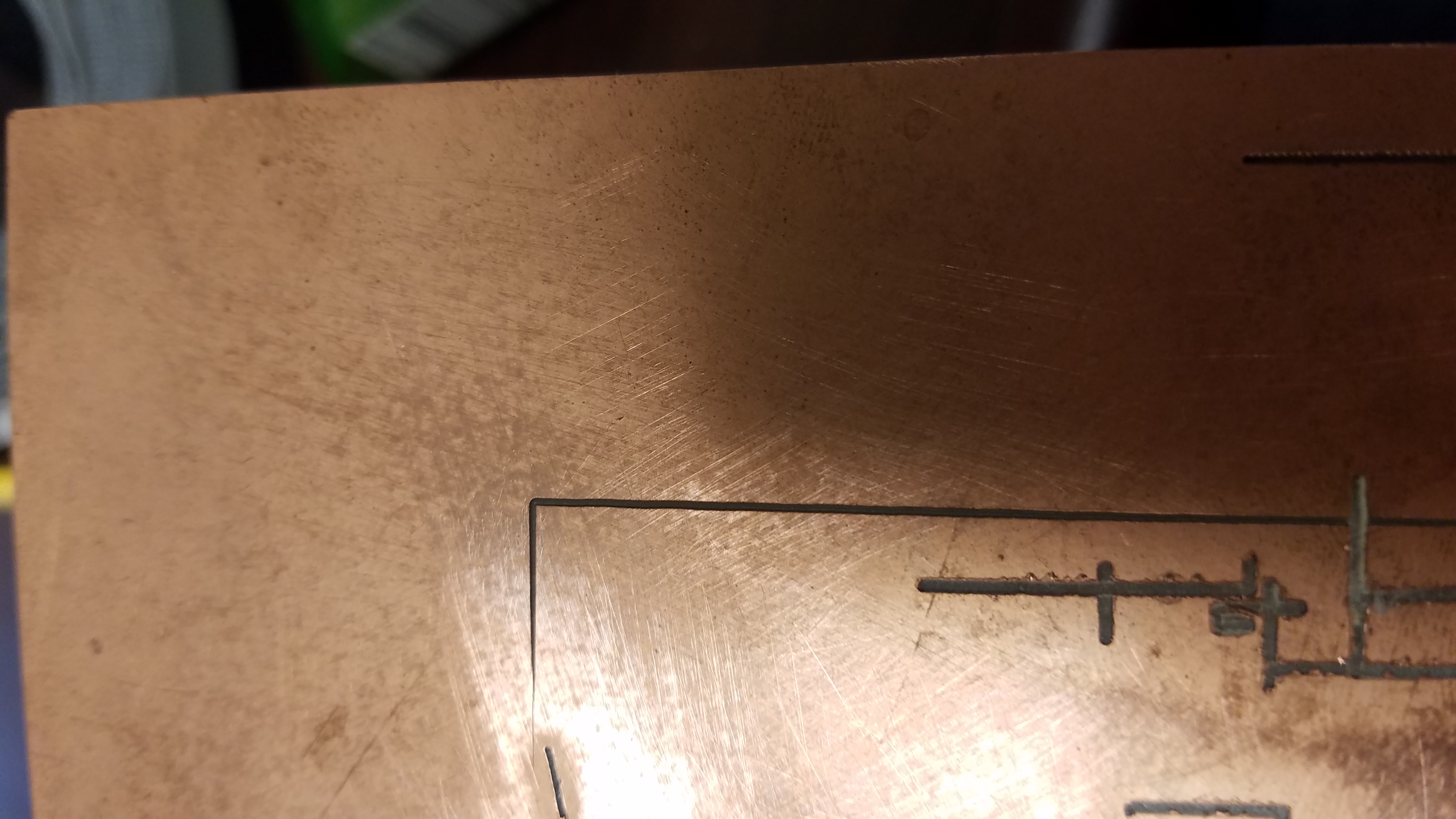
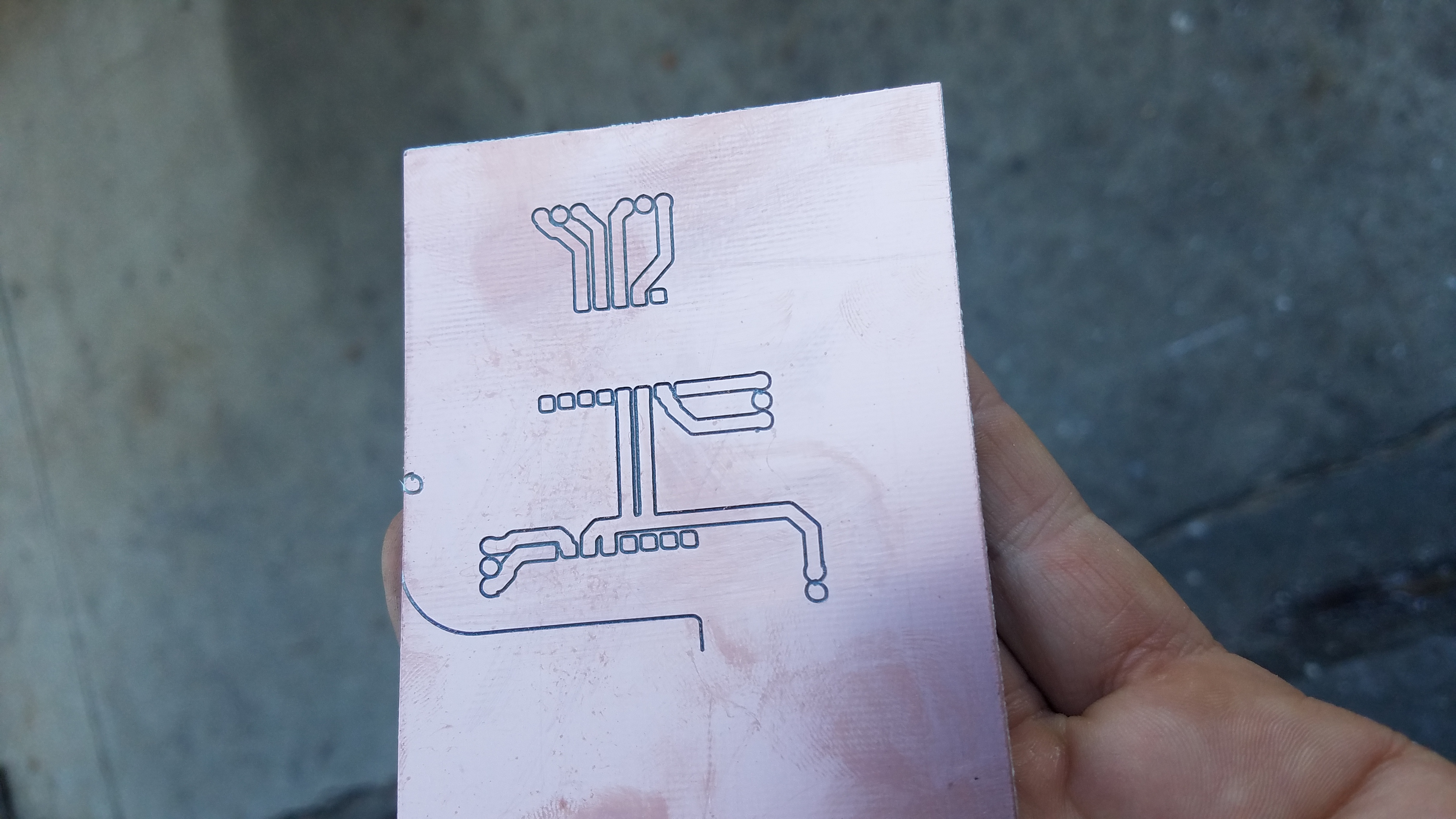
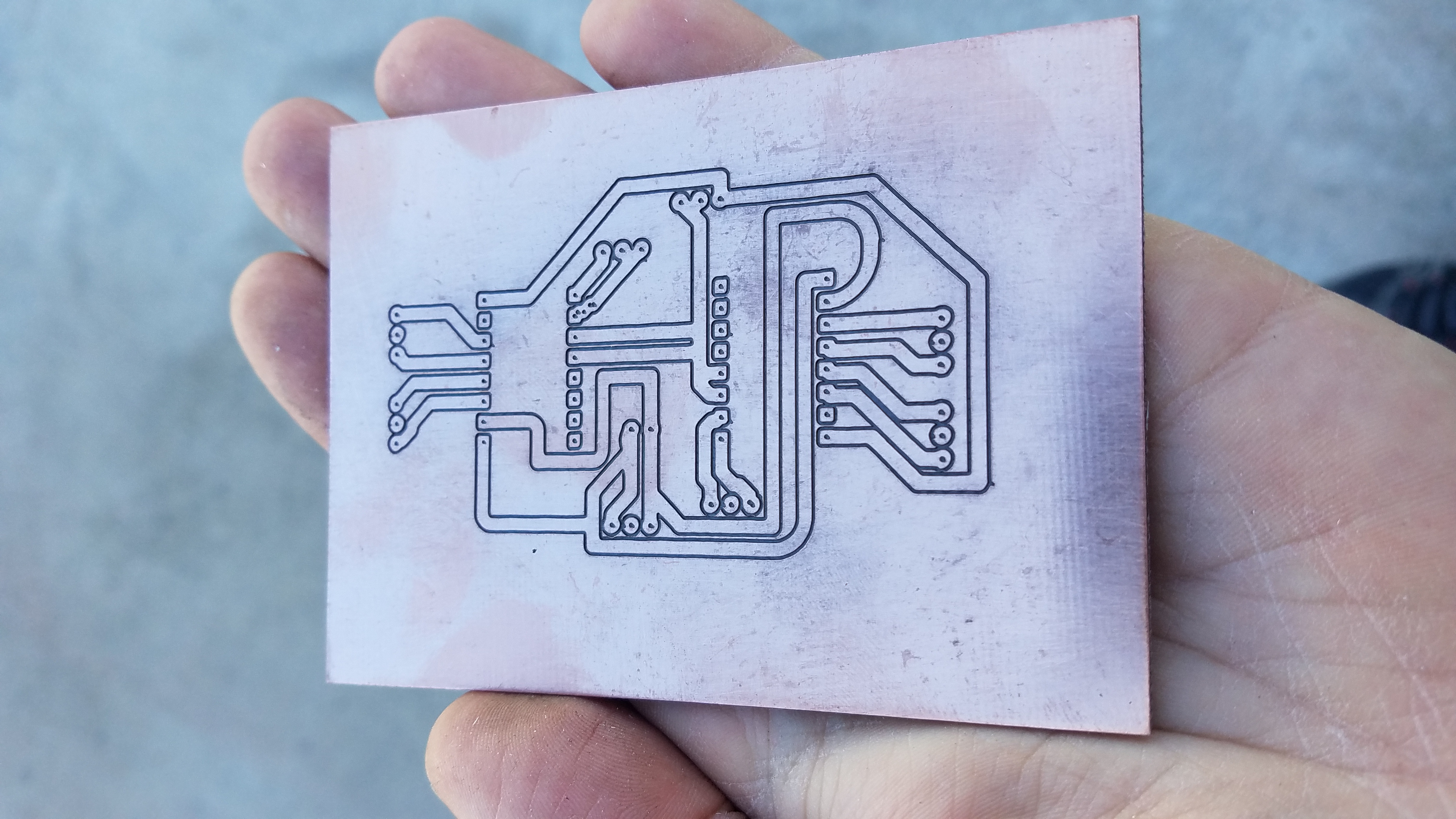
- Speed I use 3.5 and its running beautifully. The project you see above is milled in about 10 minutes.
- Flatcam cannot interpret drill files correctly. I’m still not sure why but two things I needed to do. When I imported my drill files they were miles away and huge. First type these two commands into the command line “get_sys excellon_zeros” and “set_sys excellon_zeros T”. Second open the drill file and set each hole size to .050 manually.
The floating Z
When you first try milling a pcb you will find that even the slightest unevenness between your board and the bit will result in all kinds of issues. There are two ways to solve this problem. The first is using a probe to electronically measure and calibrate for this issue over the entire board. The second is to just make the axis spring loaded and let it slide over the board and roll with the waves.
In the video I explain it and give you a good look. Those are just 6mm slide rails and a pack of miscellaneous springs. I now use a makita router due to runout issues from the cheaper router I had in this video.
Here is a video of it running.
I tried small drill bits without success and ended up using engraving bits. I had some really rough experiments where I was snapping bits left and right and making ugly cuts. Eventually I got my machine and software tuned.

Finishing them up
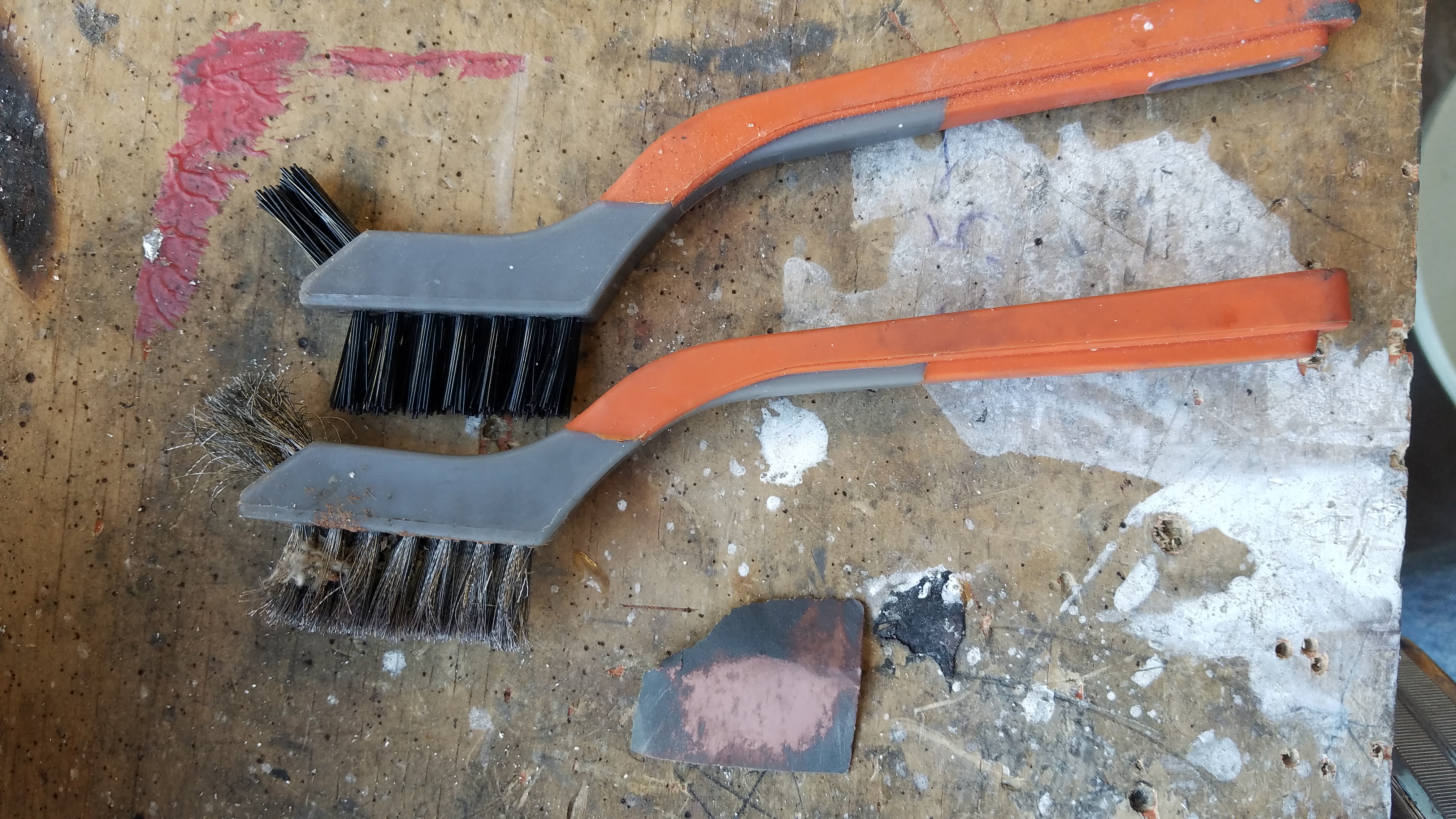
Because I use the floating z and an enraging bit I would need to change my set up to drill them out. So for now my engraving bit marks the drill holes just a bit and I drill out the marking on my drill press. One drilled I lightly sand with 1000 grit, then use a steel brush then a nylon brush.
 After I use compressed air to blow any dust off and check to make sure there the traces work with my multi meter by doing an audible continuity test.

After my designing and experimenting I can now take a circuit like this from a solder-less bread board to a finished project in about 2-4 hours.