Every project I take on teaches me something new. Oddly enough its never humility.
My recent design of an electronic speed controller for a brush less motor was a long and winding road in understanding how a motor could be controlled.
The why is simple. If you want to build a robot there are zero…I mean Zero low cost and effective solutions for actuation. Take that servo and send it back to wherever the hell it came. Its weak and expensive. However there are, separately a large selection of very powerful and cost effective motors thanks to the quad copter market.
If you have ever noticed though these motors require an electronic speed controller (esc) and the esc does quad copter things. Like accelerate in a single direction. That’s pretty much it. So I set out to make this motor do exactly what I required from it. EVERYTHING.
I chose arduino nano simply because I do not want to buy a motor control chip and rely on sourcing parts. These arduinos are cheap and I buy them in bulk becuse everything I own has an arduino hot glued to it.
The code
The code is simple in concept. Allow power to flow in and out of stator at different wires at different times in order to attract the stator coils to the magnets in a coherent and useful way.
[java]
/*
* PIN Chart PWR GND Comp/BEMF
*
* Phase A 2 3 8
* Phase B 4 5 9
* Phase C 6 7 10
*
* Phase Cycle Chart
*
* PWR GND BEMF Step Short-Step
* A C B 11010000 11011100
* B C A 11000100 11110100
* B A C 01001100 01111100
* C A B 00011100 11011100
* C B A 00110100 11110100
* A B C 01110000 01111100
*/
[/java]
My arduino used 6 pins to control 3 high and 3 low side mosfets. As you can see I attempted to use back emf but this is no good for robots because the motors cant be guaranteed to be traveling fast enough. I ended up adding low active hall sensors which work great.
The codes broad strokes are as follows:
timer_1: This is used for timing steps. Each time its called a step counter is incremented. This allows precise step timing.
timer_2: This is used for pwm. It also actually checks if a step is due to be taken and performs the pin changes.
Besides these 2 function which are precisely timed everything else is in a loop and is done as needed as fast as it can. These other functions include reading serial comm, or the hall sensors. When data is read it pushed to a variable and the timer 1 or 2 sensor will notice affect the change when appropriate. Only a thousand lines of code but between debugging the board and my code it took me a while to build up to this.
Below you can see a preliminary test.
I’m still working on the code and probably will be for some time because I have included a strain gauge to help the motor determine when it should attempt to move a load or give up.
I’m also using the hall sensors as position encoders. They work great on their own and even better when you consider the gear ratio of 39 attached to the motor.
In the below video you can see the 3d printed support for the hall sensors is attached
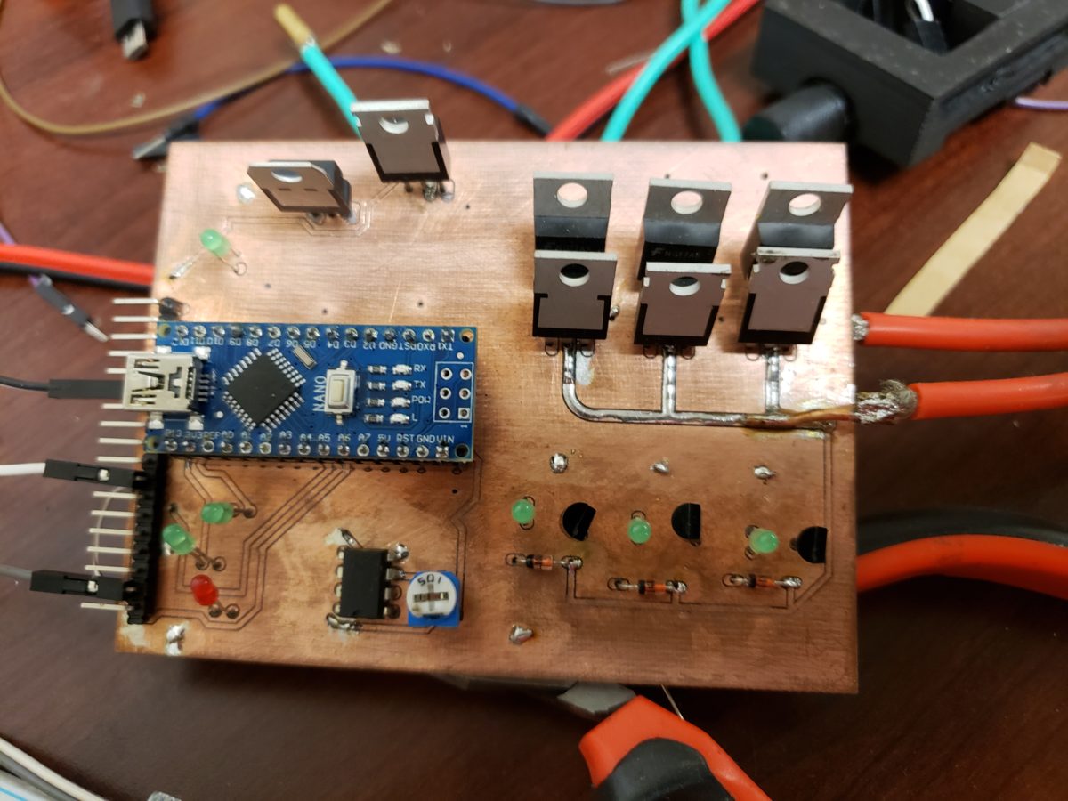
The board
I feel more comfortable coding and board design sometimes is like black magic when my calculations don’t work out and I end up just guessing for a better result. The circuit isnt too crazy. Six mosfets 3 high and 3 low side allowing power in or out the 3 connections. The hall sensors are attached to 10k pull up resistors and leds for debugging.
Below is my end goal of building a cheap, powerful actuator for robotics. This video is my first test run of connecting a motor to a gearbox. It was exciting bu the motor could only move 1 lb at 10 inches. I have since moved 10lbs at 10 inches which is as far s I know makes it one of the strongest fastest and cheapest robotic actuators ever assembled. Cant wait to get this out to people!